Rotary Drilling Luffing Cylinder
Como um dos fabricantes, fornecedores e exportadores de produtos mecânicos de cilindros hidráulicos, oferecemos cilindros hidráulicos e muitos outros produtos.
Entre em contato conosco para obter detalhes.
Correio eletrônico:sales@hydraulic-cylinders.net
Fabricante, fornecedor e exportador de cilindros hidráulicos.
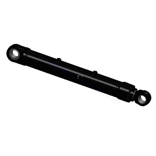
Rotary Drilling Luffing Cylinder

The rotary drilling luffing cylinder is a vital component designed to optimize the performance of rotary drilling equipment. This hydraulic cylinder plays a crucial role in the luffing mechanism, which is responsible for raising and lowering the drilling mast or boom, enabling precise positioning and efficient drilling operations.
The rotary drilling luffing cylinder is a critical component that enhances efficiency and precision in drilling operations. With its robust construction, hydraulic power and control, adjustable luffing range, and smooth movements, this hydraulic cylinder enables operators to position the drilling mast or boom accurately and achieve optimal drilling performance. By following proper usage methods and adhering to recommended maintenance practices, operators can maximize the lifespan and reliability of the rotary drilling luffing cylinder, leading to safe and efficient drilling operations. Choose this indispensable hydraulic component to optimize your drilling equipment and achieve superior results.
Rotary Drilling Luffing Cylinder Key Characteristics:
- Robust Construction and Durability:
- The rotary drilling luffing cylinder is constructed with high-quality materials, ensuring exceptional strength and durability.
- It can withstand the demanding conditions encountered in drilling operations, including heavy loads, vibrations, and harsh environments.
- Hydraulic Power and Control:
- This cylinder operates through a hydraulic control system, utilizing hydraulic power to drive the luffing mechanism.
- The hydraulic control ensures precise and responsive movement of the drilling mast or boom, allowing for accurate positioning and control.
- Adjustable Luffing Range:
- The rotary drilling luffing cylinder provides an adjustable range, enabling operators to position the drilling equipment at the desired angle or height.
- This flexibility allows for versatile drilling operations, accommodating various ground conditions and requirements.
- Smooth and Controlled Movements:
- The cylinder’s design and hydraulic control system ensure smooth and controlled movements during luffing operations.
- This precise control allows operators to maintain stability and accuracy while positioning the drilling mast or boom.
Rotary Drilling Luffing Cylinder Parameter:
| Product Name | Rotary Drilling Luffing Cylinder |
| Features: | Control the luffing angle, adjust the distance between the mast and the host |
| Bore diameter: | 125mm~250mm |
| Rod diameter: | 90mm~160mm Stroke≤1640 mm |
| Pressure: | up to 32MPa |
| Luffing Cylinder Applications: | Rotary Drilling |
Rotary Drilling Luffing Cylinder Identification Diagram:

Usage Method Of Rotary Drilling Luffing Cylinder:
- Familiarize with Controls and Safety Guidelines:
- Before operating the rotary drilling equipment, operators should thoroughly familiarize themselves with the controls and safety guidelines provided by the equipment manufacturer.
- Ensure compliance with all safety procedures and precautions to promote safe and efficient drilling operations.
- Luffing Control:
- Use the control mechanism, such as a joystick or control panel, to activate the Rotary Drilling Luffing Cylinder.
- Apply the appropriate control input to raise or lower the drilling mast or boom to the desired position.
- The cylinder will translate the hydraulic power into the required force to move the equipment smoothly and precisely.
- Positioning and Stability:
- Adjust the luffing range and position of the drilling mast or boom according to the specific drilling requirements and ground conditions.
- Maintain stability during luffing operations to ensure safe and accurate drilling performance.
- Regularly monitor the position of the equipment and make adjustments as necessary to maintain the desired drilling angle or height.
How To Bleed Air From A Hydraulic System?
Bleeding air from a hydraulic system is an important procedure to ensure optimal performance and prevent issues such as sponginess in the hydraulic components. Here’s a step-by-step guide on how to bleed air from a hydraulic system:
- Identify Air in the System:
- Check for symptoms of air in the hydraulic system, such as spongy pedal or lever feel, reduced braking or steering performance, or unusual noises.
- Confirm air presence by inspecting the fluid level in the reservoir. Air bubbles or frothy appearance indicate air in the system.
- Prepare the System:
- Ensure the hydraulic system is turned off and at a safe temperature to avoid potential injuries.
- Locate the bleed valves or fittings in the hydraulic system. These are typically found near the highest points of the system or at components prone to air entrapment, such as calipers or cylinders.
- Gather Necessary Tools:
- Depending on the system, you may need a wrench, socket set, or specialized bleed kit.
- Prepare a container to catch any fluid that may be expelled during the bleeding process.
- Start Bleeding Process:
- Begin with the hydraulic component closest to the reservoir and work your way towards the farthest component.
- Locate the bleed valve or fitting on the first component and position the container to catch the fluid.
- Open the Bleed Valve:
- Using the appropriate tool, slowly open the bleed valve or fitting.
- As fluid is released, air bubbles will escape from the system.
- Purge the Air:
- To purge the air, activate the hydraulic system by pressing the brake pedal, operating the hydraulic lever, or engaging the system as required.
- Repeat this process multiple times, holding the pedal or lever down for a few seconds before closing the bleed valve.
- Close the Bleed Valve:
- Once a steady stream of fluid without air bubbles is observed, close the bleed valve or fitting firmly.
- Ensure it is properly tightened to prevent any leaks.
- Check Fluid Level:
- Monitor the fluid level in the reservoir during the bleeding process.
- Top up the fluid as needed to maintain the recommended level.
- Repeat for Other Components:
- Move to the next hydraulic component in the system and repeat the bleeding process.
- Follow the same steps until all components have been bled.
- Test the System:
- After bleeding all components, test the hydraulic system to ensure proper operation.
- Verify that the pedal or lever feels firm and responsive, and that the system functions as expected.
Aptidão e capacidade da fábrica:
(1) Montagem
Temos uma plataforma de montagem de pesquisa e desenvolvimento independente de primeira classe. A oficina de produção de cilindros hidráulicos tem quatro linhas de montagem semiautomáticas de cilindros de elevação e uma linha de montagem automática de cilindros de inclinação, com uma capacidade de produção anual projetada de 1 milhão de peças. A oficina de cilindros especiais é equipada com várias especificações de um sistema de montagem de limpeza semiautomática com uma capacidade de produção anual projetada de 200.000 peças e equipada com famosos equipamentos de usinagem CNC, um centro de usinagem, um equipamento especial de processamento de cilindros de alta precisão, uma máquina de solda robotizada, uma máquina de limpeza automática, uma máquina de montagem automática de cilindros e uma linha de produção de pintura automática. O equipamento crítico existente é de mais de 300 conjuntos (conjuntos). A alocação ideal e o uso eficiente dos recursos do equipamento garantem os requisitos de precisão dos produtos e atendem às necessidades de alta qualidade dos produtos.


(2) Usinagem
A oficina de usinagem é equipada com um centro de torneamento de trilho inclinado personalizado, um centro de usinagem, uma máquina de brunimento de alta velocidade, um robô de soldagem e outros equipamentos relacionados, que podem lidar com o processamento de tubos de cilindros com diâmetro interno máximo de 400 mm e comprimento máximo de 6 metros.

(3) Soldagem

(4) Pintura e revestimento
Com linhas de revestimento de tinta à base de água automáticas de cilindros de pequeno e médio porte, para obter carregamento e descarregamento automáticos de robôs e pulverização automática, a capacidade projetada é de 4.000 peças por turno;
Também temos uma linha de produção de tinta semiautomática para cilindros grandes, acionada por uma corrente elétrica, com capacidade de projeto de 60 caixas por turno.


(5) Testes
Temos instalações de inspeção e bancos de teste de primeira classe para garantir que o desempenho do cilindro atenda aos requisitos.

We are one of the best hydraulic cylinder manufacturers. We can offer comprehensive hydraulic cylinders. We also provide corresponding caixas de câmbio agrícolas. Exportamos nossos produtos para clientes em todo o mundo e conquistamos uma boa reputação devido à qualidade superior de nossos produtos e ao serviço pós-venda. Convidamos clientes nacionais e estrangeiros a entrar em contato conosco para negociar negócios, trocar informações e cooperar conosco!
Faça um tour pela nossa fábrica de RV:
Faça um tour pela nossa fábrica de RV com o seguinte
Como funciona o cilindro hidráulico da empilhadeira?
Cilindro hidráulico Aplicação:
