Mobile Crane Luffing Cylinder
Como um dos fabricantes, fornecedores e exportadores de produtos mecânicos de cilindros hidráulicos, oferecemos cilindros hidráulicos e muitos outros produtos.
Entre em contato conosco para obter detalhes.
Correio eletrônico:sales@hydraulic-cylinders.net
Fabricante, fornecedor e exportador de cilindros hidráulicos.
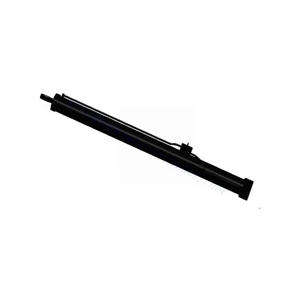
Mobile Crane Luffing Cylinder
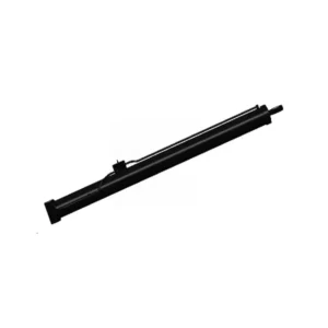
The mobile crane luffing cylinder is essential in mobile crane systems and is designed to enhance these powerful machines’ vertical reach and lifting efficiency. This hydraulic cylinder plays a crucial role in adjusting the angle of the crane’s boom, allowing operators to extend or retract the boom smoothly and precisely.
The mobile crane luffing cylinder is vital for enhancing the vertical reach, lifting efficiency, and overall performance of mobile cranes. With its robust construction, precise angle adjustment, extended vertical space, and improved lifting capacity, this hydraulic cylinder empowers operators to navigate challenging construction sites and industrial environments with ease and safety. By following the recommended usage methods and maintenance practices, operators can maximize the longevity and performance of the mobile crane luffing cylinder, contributing to increased productivity, efficiency, and operator confidence in completing various lifting tasks. Invest in this essential hydraulic component to elevate the capabilities of your mobile crane, ensuring successful and efficient operations in diverse construction and industrial applications.
Mobile Crane Luffing Cylinder Key Characteristics:
- Robust Construction:
- The mobile crane luffing cylinder is built with high-quality materials, ensuring durability, strength, and resistance to heavy loads and harsh environmental conditions.
- It is designed to withstand the rigors of demanding construction sites and maintain optimal performance over extended periods.
- Precise Angle Adjustment:
- This hydraulic cylinder enables precise angle adjustment of the crane’s boom, providing operators with fine control over vertical reach and positioning.
- It offers smooth and responsive movement, allowing for accurate load placement and minimizing the risk of collisions or accidents.
- Extended Vertical Reach:
- The mobile crane luffing cylinder extends the crane’s vertical reach by adjusting the angle of the boom.
- It enhances the crane’s flexibility in accessing elevated work areas, such as high-rise construction sites or industrial installations.
- Lifting Efficiency:
- By optimizing the angle of the boom, the luffing cylinder enhances the lifting efficiency of the mobile crane.
- It allows for better load distribution, reducing stress on the crane’s components and improving overall lifting capacity.
Mobile Crane Luffing Cylinder Parameter:
| Product Name | Mobile Crane Luffing Cylinder |
| Features: | Realizing the up-and-down pitching rotation of the boom is the main driving force for lifting |
| Bore diameter: | 100mm~560mm |
| Rod diameter: | 50mm~480mm Stroke≤5000 mm |
| Pressure: | Maximum 36MPa |
| Luffing Cylinder Applications: | Mobile Crane |
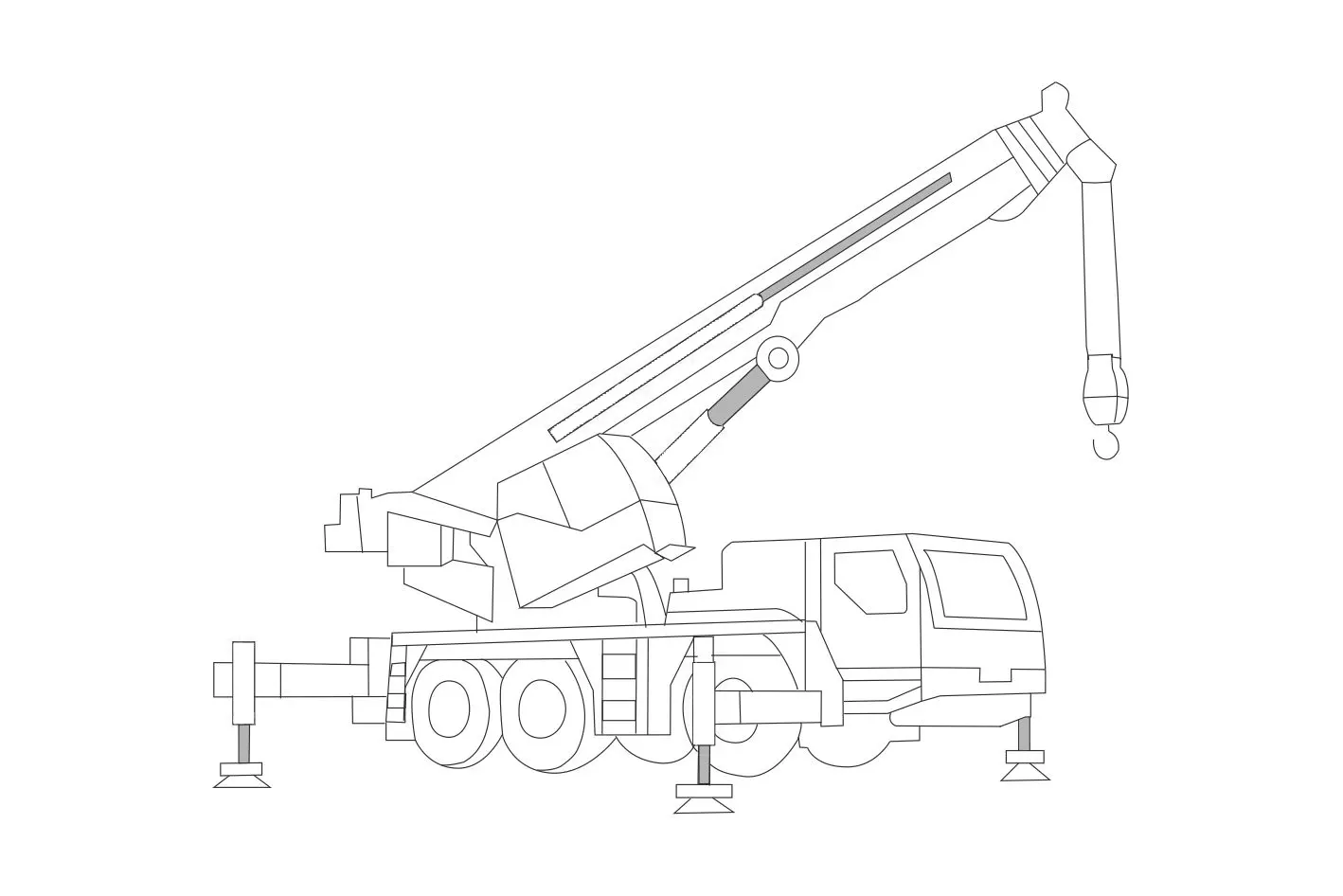
Mobile Crane Identification Diagram:
Usage Method Of Mobile Crane Luffing Cylinder:
- Precauções de segurança:
- Before operating the mobile crane, ensure all safety guidelines and regulations are followed.
- Conduct a thorough inspection of the crane and its components, including the luffing cylinder, to ensure they are in proper working condition.
- Familiarize with Controls:
- Understand the control mechanisms and operating procedures specific to your mobile crane model.
- Identify the control for adjusting the luffing angle and ensure it functions properly.
- Luffing Angle Adjustment:
- Activate the control for the luffing cylinder, typically located in the operator’s cabin.
- Use the control to extend or retract the boom, adjusting the luffing angle as required for the lifting operation.
- Follow the load charts and manufacturer’s guidelines for the appropriate luffing angles based on the load weight and radius.
- Load Placement and Monitoring:
- Once the desired luffing angle is achieved, carefully position the load using the crane’s other controls, such as the hoist and swing mechanisms.
- Continuously monitor the load and adjust the luffing angle to maintain stability and safety during the lifting operation.
How To Release Pressure On Hydraulic System?
Releasing pressure from a hydraulic system is a necessary safety procedure that should be followed whenever maintenance or repair work is performed. Here are the general steps to release pressure from a hydraulic system:
- Identify the Power Source:
- Determine the power source supplying pressure to the hydraulic system, such as an electric motor, an engine-driven pump, or a manual pump.
- Locate the power switch or control valve associated with the power source.
- Shut Down the Power Source:
- Turn off the power switch or control valve to stop the power source from supplying pressure to the hydraulic system.
- If an engine powers the hydraulic system, shut off the engine completely.
- Engage the System Controls:
- Operate the control valves or switches on the hydraulic system to move actuators or components to neutral or resting positions.
- This step helps relieve residual pressure and allows the hydraulic fluid to flow back to the reservoir.
- Release Pressure at the Pump:
- If the hydraulic system has a pump with a pressure relief valve, locate the valve.
- Turn the pressure relief valve counterclockwise (or as specified by the manufacturer) to release pressure gradually.
- If available, check the system pressure gauge to ensure that pressure is relieved.
- Bleed Air from the System:
- Some hydraulic systems may have air trapped within the system, which can cause pressure buildup.
- To release air, open the air bleed valves or loosen fittings strategically to allow air to escape.
- Start from the lowest points in the system and work your way up to the highest points.
- Keep bleeding the system until a steady flow of hydraulic fluid is observed without air bubbles.
- Verify Pressure Release:
- Check the pressure gauge, if available, to ensure that the pressure has been fully released.
- Double-check the system controls to ensure that all actuators and components are neutral or resting.
Aptidão e capacidade da fábrica:
(1) Montagem
Temos uma plataforma de montagem de pesquisa e desenvolvimento independente de primeira classe. A oficina de produção de cilindros hidráulicos tem quatro linhas de montagem semiautomáticas de cilindros de elevação e uma linha de montagem automática de cilindros de inclinação, com uma capacidade de produção anual projetada de 1 milhão de peças. A oficina de cilindros especiais é equipada com várias especificações de um sistema de montagem de limpeza semiautomática com uma capacidade de produção anual projetada de 200.000 peças e equipada com famosos equipamentos de usinagem CNC, um centro de usinagem, um equipamento especial de processamento de cilindros de alta precisão, uma máquina de solda robotizada, uma máquina de limpeza automática, uma máquina de montagem automática de cilindros e uma linha de produção de pintura automática. O equipamento crítico existente é de mais de 300 conjuntos (conjuntos). A alocação ideal e o uso eficiente dos recursos do equipamento garantem os requisitos de precisão dos produtos e atendem às necessidades de alta qualidade dos produtos.


(2) Usinagem
A oficina de usinagem é equipada com um centro de torneamento de trilho inclinado personalizado, um centro de usinagem, uma máquina de brunimento de alta velocidade, um robô de soldagem e outros equipamentos relacionados, que podem lidar com o processamento de tubos de cilindros com diâmetro interno máximo de 400 mm e comprimento máximo de 6 metros.

(3) Soldagem

(4) Pintura e revestimento
Com linhas de revestimento de tinta à base de água automáticas de cilindros de pequeno e médio porte, para obter carregamento e descarregamento automáticos de robôs e pulverização automática, a capacidade projetada é de 4.000 peças por turno;
Também temos uma linha de produção de tinta semiautomática para cilindros grandes, acionada por uma corrente elétrica, com capacidade de projeto de 60 caixas por turno.


(5) Testes
Temos instalações de inspeção e bancos de teste de primeira classe para garantir que o desempenho do cilindro atenda aos requisitos.

We are one of the best hydraulic cylinder manufacturers. We can offer comprehensive hydraulic cylinders. We also provide corresponding caixas de câmbio agrícolas. Exportamos nossos produtos para clientes em todo o mundo e conquistamos uma boa reputação devido à qualidade superior de nossos produtos e ao serviço pós-venda. Convidamos clientes nacionais e estrangeiros a entrar em contato conosco para negociar negócios, trocar informações e cooperar conosco!
Faça um tour pela nossa fábrica de RV:
Faça um tour pela nossa fábrica de RV com o seguinte
Como funciona o cilindro hidráulico da empilhadeira?
Cilindro hidráulico Aplicação:
