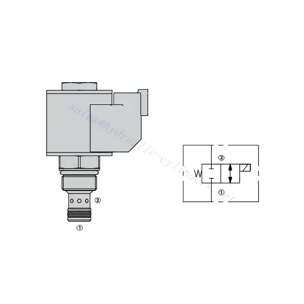
30SD08-24 Solenoid Directional Valve
Jako jeden z producentów, dostawców i eksporterów produktów mechanicznych, oferujemy cylindry hydrauliczne i wiele innych produktów.
Prosimy o kontakt w celu uzyskania szczegółowych informacji.
Poczta:sales@hydraulic-cylinders.net
Producent dostawca eksporter siłowników hydraulicznych.
30SD08-24 Solenoid Directional Valve

We are introducing the 30SD08-24 solenoid directional valve, an advanced hydraulic component designed to provide precise control and efficient operation in various industrial applications. This valve is engineered to optimize fluid flow direction, allowing for smooth and reliable hydraulic system performance.
The 30SD08-24 solenoid directional valve offers enhanced precision and efficiency for hydraulic systems. With its precise fluid flow control, high flow capacity, quick response time, and robust construction, this valve provides optimal performance and reliability. By following the recommended usage methods and maintenance guidelines, you can maximize the potential of the 30SD08-24 solenoid directional valve and achieve improved precision, efficiency, and productivity in your hydraulic applications. Upgrade your hydraulic system today with the 30SD08-24 solenoid directional valve and experience enhanced control and optimized performance.
30SD08-24 Solenoid Directional Valve Characteristics:
- Precise Fluid Flow Control:
- The 30SD08-24 solenoid directional valve offers exceptional precision in controlling fluid flow direction, ensuring accurate system operation.
- It allows for seamless adjustment of fluid flow rates, facilitating optimal performance and responsiveness in various industrial applications.
- High Flow Capacity:
- With its high flow capacity, this valve can handle substantial fluid volumes, making it ideal for applications that require efficient flow control.
- The valve’s ability to accommodate high flow rates ensures smooth and reliable operation, even in demanding hydraulic systems.
- Quick Response Time:
- Equipped with advanced solenoid technology, the 30SD08-24 solenoid directional valve delivers rapid response times, enabling precise control and adjustments.
- The valve’s quick response time enhances system efficiency, allowing for swift and accurate changes in fluid flow direction.
- Robust Construction:
- Built to withstand challenging operating conditions, the 30SD08-24 solenoid directional valve boasts a rugged construction that ensures long-lasting performance.
- Its durable materials and robust design minimize downtime, reducing maintenance requirements and optimizing system uptime.
30SD08-24 Solenoid Directional Valve Parameter:
| Rated pressure | 207 bar(3000 psi) | |
| Peak flow | See performance chart | |
| Fluid | Mineral-based or synthetics with lubricating properties | |
| Rango de temperatura del fluido ℃ | -54 a 107 ℃ (Juntas de poliuretano) | |
| -40 a 100 ℃ (Juntas de Buna N) | ||
| -26 en 204 ℃ (Juntas de fluorocarbono) | ||
| Viscosity range | 7.4 to 420 mm2/s | |
| Degree of contamination | The minimum pollution level is ISO4406 level 20/18/14, and level 17/15/13 is recommended to prolong the service life | |
| Internal Leakage | ≤ 0.15 mL/min (3 drops/min) @207bar | |
| Cavity | VC08-2 | |
| Coil Duty Rating | Continuous from 85% to 115% of nominal voltage | |
| Initial Coil Current Draw at 20℃ | 1.4A at 12VDC; 0.7A at 24VDC | |
| Minimum pull-in voltage | 85% of nominal at 207 bar (3000 psi) | |
30SD08-24 Solenoid Directional Valve Advantages:
• Continuous-duty rated coil
• Efficient wet-armature construction
• Cartridges are voltage interchangeable
• Optional waterproof E-Coils rated up to IP69K
• Industry common cavity
• Hardened parts for long life and low leakage
Usage Method Of 30SD08-24 Solenoid Directional Valve:
- System Evaluation:
- Begin by assessing your hydraulic system’s requirements, including flow rates, pressure levels, and system dynamics.
- Determine if the 30SD08-24 Solenoid Directional Valve aligns with your system’s specific needs, considering its precision and flow capacity.
- Valve Selection:
- Select the appropriate variant of the 30SD08-24 Solenoid Directional Valve based on your system parameters and performance requirements.
- Consider factors like flow capacity, pressure ratings, and compatibility with other system components to ensure optimal functionality.
- Installation:
- Follow the manufacturer’s installation instructions meticulously to ensure proper placement and secure valve mounting.
- Position the valve correctly within the hydraulic system, considering fluid flow direction and accessibility for maintenance purposes.
- Electrical Connections:
- Connect the solenoid valve to the designated power source according to the manufacturer’s specifications.
- Ensure that the electrical connections are secure and comply with safety standards and regulations.
How To Install A Hydraulic Pressure Relief Valve?
Installing a hydraulic pressure relief valve is a crucial step in ensuring the safety and proper functioning of a hydraulic system. Here’s a step-by-step guide on how to install a hydraulic pressure relief valve:
- Identify the Valve: Determine the specific type and model of the hydraulic pressure relief valve you work with. Ensure it is suitable for your application and compatible with your hydraulic system requirements.
- Gather the Required Tools and Materials: Collect the necessary tools and materials, including appropriate hydraulic fittings, adapters, wrenches, Teflon tape (thread sealant), and a pressure gauge if needed. Refer to the manufacturer’s instructions for any specific tools or components required.
- Prepare the Hydraulic System: Shut down the hydraulic system and relieve pressure by activating the relief valve or retracting hydraulic cylinders. This step is crucial for safety and prevents accidental movement or hydraulic fluid release.
- Identify the Pressure Relief Point: Determine the optimal location to install the hydraulic pressure relief valve in your hydraulic system. It should be positioned downstream of the pump before any sensitive components to protect them from excessive pressure. Consult the hydraulic system schematic or seek professional advice if necessary.
- Mount the Valve: Securely mount the hydraulic pressure relief valve in the chosen location using appropriate brackets or clamps. Ensure the valve is positioned correctly, aligning the inlet and outlet ports with the flow direction. Follow the manufacturer’s instructions for specific mounting requirements.
- Connect the Inlet and Outlet Ports: Attach hydraulic hoses or tubing to the inlet and outlet ports of the relief valve. Use suitable hydraulic fittings and adapters to create a leak-free connection. Apply Teflon tape or thread sealant to the male threads of the fittings to ensure a secure and sealed connection. Tighten the connections using wrenches to avoid leaks, but be careful not to overtighten.
- Set the Pressure Relief Setting: Most hydraulic pressure relief valves come with an adjustable pressure relief setting. Adjust the relief valve to the desired pressure relief point using the manufacturer’s guidelines. Some valves may require a pressure gauge to accurately set the relief pressure. Install the pressure gauge temporarily, if needed, and adjust the relief valve until the desired pressure is achieved.
- Test the System: Once the hydraulic pressure relief valve is installed, slowly restore hydraulic system pressure. Monitor the pressure gauge or observe the system behavior to ensure that the relief valve functions correctly. The relief valve should open and divert excess pressure when it reaches the set point, preventing damage to the system.
- Monitor and Maintain: Regularly inspect the hydraulic pressure relief valve for any signs of leakage, damage, or reduced performance. Clean the valve and surrounding area to remove dirt and debris that may affect its operation. Follow the manufacturer’s recommended maintenance schedule and guidelines to ensure optimal performance and longevity.
Możliwości i pojemność fabryki:
(1) Montaż
Dysponujemy najwyższej klasy niezależną platformą badawczo-rozwojową. Warsztat produkcji siłowników hydraulicznych posiada cztery półautomatyczne linie montażowe siłowników podnoszących i jedną automatyczną linię montażową siłowników przechyłu, o projektowanej rocznej zdolności produkcyjnej 1 miliona sztuk. Specjalny warsztat cylindrów jest wyposażony w różne specyfikacje półautomatycznego systemu montażu czyszczącego o projektowanej rocznej zdolności produkcyjnej 200 000 i wyposażony w słynny sprzęt do obróbki CNC, centrum obróbcze, specjalny sprzęt do precyzyjnej obróbki cylindrów, robot spawalniczy, automatyczna maszyna czyszcząca, automatyczna maszyna do montażu cylindrów i automatyczna linia produkcyjna do malowania. Istniejący krytyczny sprzęt składa się z ponad 300 zestawów. Optymalna alokacja i efektywne wykorzystanie zasobów sprzętowych zapewniają wymagania dotyczące dokładności produktów i spełniają potrzeby wysokiej jakości produktów.


(2) Obróbka
Warsztat obróbki skrawaniem jest wyposażony w niestandardowe centrum tokarskie z pochyloną szyną, centrum obróbcze, szybkobieżną honownicę, robota spawalniczego i inny powiązany sprzęt, który może obsługiwać przetwarzanie rur cylindrycznych o maksymalnej średnicy wewnętrznej 400 mm i maksymalnej długości 6 metrów.

(3) Spawanie

(4) Malowanie i powlekanie
Z małymi i średnimi automatycznymi liniami do powlekania farbami na bazie wody, w celu osiągnięcia automatycznego załadunku i rozładunku robota oraz automatycznego natryskiwania, wydajność projektowa 4000 sztuk na zmianę;
Posiadamy również półautomatyczną linię do produkcji farb do dużych cylindrów napędzaną łańcuchem napędowym, o wydajności 60 skrzyń na zmianę.


(5) Testowanie
Dysponujemy najwyższej klasy urządzeniami kontrolnymi i stanowiskami testowymi, aby zapewnić, że wydajność cylindra spełnia wymagania.

We are one of the best hydraulic cylinder manufacturers. We can offer comprehensive hydraulic cylinders. We also provide corresponding przekładnie rolnicze. Eksportowaliśmy nasze produkty do klientów na całym świecie i zdobyliśmy dobrą reputację dzięki najwyższej jakości produktów i usług posprzedażnych. Zapraszamy klientów w kraju i za granicą do kontaktu z nami w celu negocjacji biznesowych, wymiany informacji i współpracować z nami!
Zapraszamy na wycieczkę po naszej fabryce VR:
Wybierz się na wycieczkę po naszej fabryce VR z następującymi elementami
Jak działa siłownik hydrauliczny wózka widłowego?
Siłownik hydrauliczny Zastosowanie:
