Aerial Work Platform Rotary Actuator
유압 실린더 제조업체, 공급 업체 및 기계 제품 수출 업체 중 하나로서 유압 실린더 및 기타 여러 제품을 제공합니다.
자세한 내용은 당사에 문의해 주세요.
메일:sales@hydraulic-cylinders.net
유압 실린더 제조업체 공급 업체 수출.
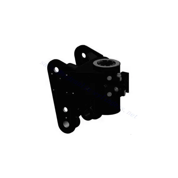
Aerial Work Platform Rotary Actuator
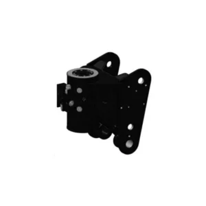
HBM series rotary actuator is a rotary actuator independently designed and developed for the arms control of articulated aerial work platforms. According to customer installation and performance requirements, the corresponding customized design can be realized to ensure the adaptability and flexibility of operation.
Based on the metric unit design, the unique seal and construction allow for a low coefficient of friction and high output torque. In addition, finite element analysis and durability testing contribute to the stability and reliability of the product. Compared with similar products on the market, the HBM series rotary actuator under the same product size, the output torque is increased by 10% ~ 20%, the cracking pressure is reduced by 50%, the operation is stable, the efficiency is higher, the cracking pressure is better, and finally ensure the safe, reliable and efficient work of the high-altitude working platform.
Aerial Work Platform Rotary Actuator Key Characteristics:
- Low Friction Coefficient:
- The critical component of the HBM series rotary actuator – the spiral spline for rotation and torque transmission,
features excellent precision, balanced stress distribution, and stable transmission. With the low-friction axial bearings and a unique sealing system design, the HBM series rotary actuator has a low friction coefficient during transmission.
- High Output Torque:
- Through continuous innovative research and validations, the HBM series rotary actuator is designed compactly to fully use the limited internal space and transmit high output torque via fluid pressure. Compared to similar products, the HBM series rotary actuator provides a 10% to 20% higher output torque under the same product size.
- Long Service Life:
- Comprehensive analysis and calculation on each size of the HBM rotary actuator are implemented with the assistance of FEA software during the design process. Besides, product optimization is continuously carried out to ensure that each product size can meet the long service life requirements.
- Except for regular factory tests, two dedicated rotary actuator endurance test benches are available for tests according to customer and application requirements, ensuring excellent durability and long service life.
Aerial Work Platform Rotary Actuator Parameter:
| Product Name | Aerial Work Platform Rotary Actuator |
| Features: | Realize platform and crank arm swing |
| Torque: | 500~5000N.m |
| Swing angle: | 0~360° |
| Pressure: | 21MPa(standard working pressure) |
| Rotary Actuator Applications: | Aerial Work Platform |
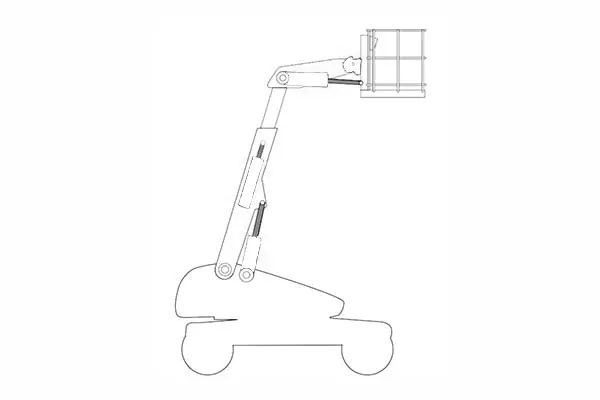
Aerial Work Platform Identification Diagram:
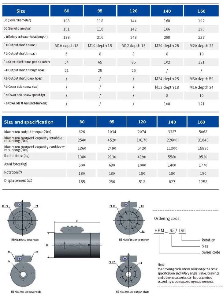
Aerial Work Platform Rotary Actuator Size And Specification:
Usage Method Of Aerial Work Platform Rotary Actuator:
- Actuator Installation:
- Follow the manufacturer’s instructions for proper installation of the aerial work platform rotary actuator.
- Ensure the actuator is securely mounted to the aerial work platform’s structure, providing a stable and reliable connection.
- Electrical and Hydraulic Connection:
- Connect the actuator to the electrical and hydraulic systems of the aerial work platform according to the provided guidelines.
- Ensure all connections are secure and properly sealed to prevent leaks or electrical malfunctions.
- Rotation Control:
- Utilize the control panel or interface provided to control the rotational movement of the aerial work platform.
- Follow the recommended operating procedures and safety guidelines for smooth and precise rotation.
- Safety Considerations:
- Before operating the aerial work platform, familiarize yourself with the safety features and emergency procedures.
- Ensure that all operators receive proper training on the safe operation of the platform and the aerial work platform rotary actuator.
How To Bleed Air From A Hydraulic System?
Bleeding air from a hydraulic system is a crucial maintenance procedure to ensure optimal performance and prevent spongy or inconsistent hydraulic operation. Here’s a step-by-step guide on how to bleed air from a hydraulic system:
- Identify Bleed Points:
- Locate the bleed points in the hydraulic system. These are typically found at high energies, such as on top of hydraulic cylinders, control valves, or pump reservoirs.
- Consult the hydraulic system’s manual or manufacturer’s guidelines to identify the specific bleed points for your system.
- Prepare the System:
- Turn off the power to the hydraulic system and relieve pressure by lowering or retracting hydraulic cylinders or releasing the pressure valve.
- Ensure you have the necessary tools and safety equipment to perform the bleeding process, including safety goggles and gloves.
- Position a Collection Container:
- Place a suitable container or drain pan beneath the bleed point to collect any hydraulic fluid that may be released during the bleeding process.
- This will help prevent spills and keep your work area clean.
- Open the Bleed Valve:
- Slowly and partially open the bleed valve at the designated bleed point using an appropriate wrench or tool.
- Be cautious not to fully remove the valve at this stage; instead, create a small opening to allow air and fluid to escape.
- Begin Bleeding:
- With the bleed valve partially open, activate the hydraulic system by turning it on or operating the relevant controls.
- Allow the hydraulic fluid to flow through the system, pushing out any trapped air bubbles. You will notice air and fluid escaping through the partially opened bleed valve.
- Monitor and Repeat:
- Monitor the fluid flow and observe any air bubbles escaping from the bleed valve.
- Once the fluid flow is consistent and free of air bubbles, close the bleed valve tightly to prevent any further air from entering the system.
- If air bubbles persist, repeat the bleeding process by partially opening the bleed valve again and allowing more fluid to flow through until the air is eliminated.
- Check Fluid Levels:
- After bleeding the air, check the hydraulic fluid level in the system’s reservoir or tank.
- Add additional fluid if necessary to maintain the recommended fluid level.
- Test and Verify:
- With the bleeding process completed and the hydraulic system reassembled, test the system’s operation to ensure smooth and consistent hydraulic performance.
- Verify that there are no unusual sounds or vibrations and that the system responds correctly to control inputs.
Capability & Capacity Of Factory:
(1) Assembly
We have a first-class independent research and development assembly platform. The hydraulic cylinder production workshop has four semi-automatic lifting cylinder assembly lines and one automatic tilt cylinder assembly line, with a designed annual production capacity of 1 million pieces. The special cylinder workshop is equipped with various specifications of a semi-automatic cleaning assembly system with a designed annual production capacity of 200,000 and equipped with famous CNC machining equipment, a machining center, a high-precision cylinder processing special equipment, a robot welding machine, an automatic cleaning machine, automatic cylinder assembly machine, and automatic painting production line. Existing critical equipment of more than 300 sets (sets). The optimal allocation and efficient use of equipment resources ensure the accuracy requirements of products and meet the high-quality needs of products.


(2) Machining
The machining shop is equipped with a customized inclined rail turning center, machining center, high-speed honing machine, welding robot, and other related equipment, which can handle the processing of cylinder tubes with a maximum inner diameter of 400mm and a maximum length of 6 meters.

(3) Welding

(4) Painting & coating
With small and medium-sized cylinder automatic water-based paint coating lines, to achieve automatic robot loading and unloading and automatic spraying, the design capacity of 4000 pieces per shift;
We also have a semi-automatic paint production line for large cylinders powered by a power chain, with 60 cases per shift design capacity.


(5) Testing
We have first-class inspection facilities and test beds to ensure that the performance of the cylinder meets the requirements.

We are one of the best hydraulic cylinder manufacturers. We can offer comprehensive hydraulic cylinders. We also provide corresponding agricultural gearboxes. We have exported our products to clients worldwide and earned a good reputation because of our superior product quality and after-sales service. We welcome customers at home and abroad to contact us to negotiate business, exchange information, and cooperate with us!
Take a Tour of Our VR Factory:
Take a tour of our VR factory with the following
How Does Forklift Hydraulic Cylinder Work?
Hydraulic Cylinder Application:
