Pile Driving Barge Luffing Cylinder
En tant que fabricant, fournisseur et exportateur de produits mécaniques, nous proposons des vérins hydrauliques et de nombreux autres produits.
N'hésitez pas à nous contacter pour plus de détails.
Courrier :sales@hydraulic-cylinders.net
Fabricant fournisseur exportateur de vérins hydrauliques.
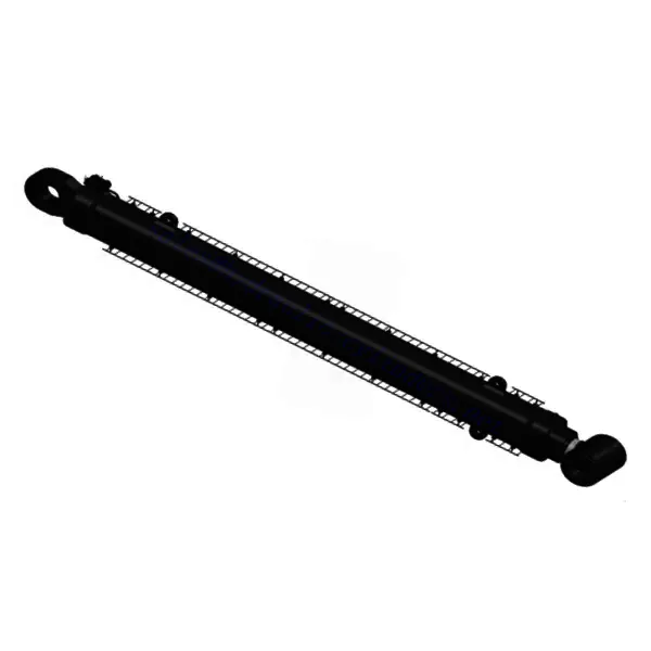
Pile Driving Barge Luffing Cylinder
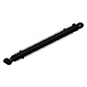
The Pile Driving Barge Luffing Cylinder is a vital component designed to optimize the performance and efficiency of pile driving operations in marine construction projects. This innovative hydraulic cylinder plays a crucial role in controlling the luffing motion of the barge’s boom, allowing for precise positioning of piles. With its exceptional features and robust construction, the Pile Driving Barge Luffing Cylinder is the ultimate solution for marine construction companies seeking improved productivity and accuracy.
The Pile Driving Barge Luffing Cylinder is a reliable and efficient hydraulic component designed to enhance the efficiency and accuracy of pile driving operations in marine construction projects. With its robust construction, precise luffing control, and easy integration, it improves productivity and provides precise positioning of piles. By following the recommended usage methods and implementing regular maintenance practices, marine construction companies can maximize the longevity and performance of this essential component, contributing to the success of their projects.
Drilling Platform Steel Wire Rope Tensioner Cylinder Key Characteristics:
- Robust Construction: The pile driving barge luffing cylinder is built with high-quality materials to withstand the harsh marine environment. Its durable construction ensures longevity and minimizes maintenance requirements, even in demanding conditions.
- Precise Luffing Control: This cylinder provides precise control over the luffing motion of the barge’s boom. Operators can adjust and maintain the desired boom angle, ensuring accurate pile placement and optimized construction efficiency.
- Hydraulic Power: Powered by a hydraulic system, the pile driving barge luffing cylinder utilizes pressurized fluids to generate the force required for luffing control. The hydraulic mechanism provides smooth and responsive operation, allowing for precise adjustments and increased productivity.
- Easy Installation and Integration: The pile driving barge luffing cylinder is designed for easy installation and integration into existing pile driving systems. Its compact size and versatile mounting options facilitate seamless incorporation, minimizing downtime during installation.
Pile Driving Barge Luffing Cylinder Parameter:
| Product Name | Pile Driving Barge Luffing Cylinder |
| Features: | swing the pile frame and bear the load, and the external force received is not only large but also complex |
| Bore diameter: | Up to 1400mm |
| Rod diameter: | Up to 900mm Stroke up to 15500mm |
| Thrust force: | 28465KN (pressure 25MPa) |
| Applications: | Jack-up Offshore Platform |
Rod diameter: up to 900mm
Stroke up to 15500mm
(pressure 25MPa)
Pile Driving Barge Cylinder Application:

Usage Method Of Pile Driving Barge Luffing Cylinder:
- Pre-Installation Inspection: Before installing the Pile Driving Barge Luffing Cylinder, conduct a thorough inspection of the cylinder and associated components. Ensure that all parts are in good condition, and verify that the boom is properly aligned and secured.
- Mounting and Connection: Install the luffing cylinder in the designated location on the pile driving barge, using appropriate mounting brackets and hardware. Connect the hydraulic lines to the cylinder, ensuring proper alignment and secure connections.
- Hydraulic System Activation: Activate the hydraulic system, ensuring proper fluid levels and pressure. Follow the manufacturer’s instructions for operating the hydraulic controls and adjusting the luffing motion.
- Luffing Adjustment: Use the hydraulic controls to adjust the luffing motion of the barge’s boom. Monitor the boom angle closely and make precise adjustments as necessary to achieve the desired pile placement and construction efficiency.
How Are Hydraulic Cylinders Made?
Hydraulic cylinders are manufactured through a series of processes that involve precision engineering, machining, and assembly. The exact manufacturing process may vary depending on the specific type and size of the hydraulic cylinder, as well as the manufacturer’s techniques and equipment. However, here is a general overview of how hydraulic cylinders are made:
- Design and Engineering: The first step in manufacturing a hydraulic cylinder is the design and engineering phase. Engineers analyze the requirements and specifications of the cylinder, considering factors such as load capacity, pressure ratings, stroke length, and mounting options. Computer-aided design (CAD) software is often used to create detailed 3D models and technical drawings.
- Material Selection: Once the design is finalized, the appropriate materials are selected for constructing the hydraulic cylinder. Common materials used include high-strength steel for the cylinder barrel and piston rod, cast iron or aluminum for end caps, and various seals and O-rings made of elastomers or other suitable materials.
- Cylinder Barrel Production: The cylinder barrel is typically produced through honing. This involves machining the inner surface of a seamless steel tube to achieve the desired smoothness and dimensional accuracy. The honing process creates the precise cylinder bore where the piston will move.
- Piston Rod Production: The piston rod extends from one end of the cylinder and is usually made from a high-strength steel bar. The rod is machined to the required dimensions, including precision grinding of the surface finish, to ensure smooth operation and resistance to wear.
- Machining and Component Fabrication: Various components of the hydraulic cylinder, such as end caps, piston heads, and mounting brackets, are fabricated through machining processes. CNC (Computer Numerical Control) machines are commonly used to accurately shape and drill holes in the components according to the design specifications.
- Surface Treatment: Depending on the application and requirements, certain surfaces of the hydraulic cylinder may undergo additional treatments. These can include processes like heat treatment to improve strength and durability, plating or coating for corrosion resistance, or specialized surface treatments such as hard chrome plating on the piston rod for increased wear resistance.
- Assembly: The hydraulic cylinder is assembled once all the necessary components are fabricated and treated. This involves carefully fitting the cylinder barrel, piston, piston rod, seals, and other parts together. Precise alignment and proper sealing are essential to ensure optimal performance and prevent leaks.
- Testing and Quality Assurance: Before the hydraulic cylinder is ready for distribution, it undergoes rigorous testing to ensure it meets the required standards and specifications. This can include pressure testing, functional testing, and dimensional inspections. Quality assurance procedures are implemented to maintain consistent quality throughout the manufacturing process.
- Packaging and Distribution: The completed hydraulic cylinders are packaged securely to protect them during transportation. They are then distributed to customers or stored in inventory for future use.
Capacité de l'usine :
(1) Assemblage
We have a first-class independent research and development assembly platform. The hydraulic cylinder production workshop has four semi-automatic lifting cylinder assembly lines and one automatic tilt cylinder assembly line, with a designed annual production capacity of 1 million pieces. The special cylinder workshop is equipped with various specifications of a semi-automatic cleaning assembly system with a designed annual production capacity of 200,000 and equipped with famous CNC machining equipment, a machining center, a high-precision cylinder processing special equipment, a robot welding machine, an automatic cleaning machine, automatic cylinder assembly machine, and automatic painting production line. Existing critical equipment of more than 300 sets (sets). The optimal allocation and efficient use of equipment resources ensure the accuracy requirements of products and meet the high-quality needs of products.


(2) Usinage
L'atelier d'usinage est équipé d'un centre de tournage sur rail incliné personnalisé, d'un centre d'usinage, d'une machine à honer à grande vitesse, d'un robot de soudage et d'autres équipements connexes, qui peuvent traiter des tubes cylindriques d'un diamètre intérieur maximal de 400 mm et d'une longueur maximale de 6 mètres.

(3) Soudage

(4) Peinture et revêtement
Avec des lignes de revêtement de peinture à base d'eau automatiques à cylindre de petite et moyenne taille, pour réaliser le chargement et le déchargement automatiques par robot et la pulvérisation automatique, la capacité de conception est de 4 000 pièces par équipe ;
Nous disposons également d'une ligne de production de peinture semi-automatique pour gros cylindres, alimentée par une chaîne de traction, d'une capacité de conception de 60 caisses par équipe.


(5) Essais
Nous disposons d'installations d'inspection et de bancs d'essai de premier ordre pour garantir que les performances de la bouteille sont conformes aux exigences.

We are one of the best hydraulic cylinder manufacturers. We can offer comprehensive hydraulic cylinders. We also provide corresponding boîtes de vitesses agricoles. We have exported our products to clients worldwide and earned a good reputation because of our superior product quality and after-sales service. We welcome customers at home and abroad to contact us to negotiate business, exchange information, and coopérer avec nous!
Visitez notre usine de RV :
Visitez notre usine de RV avec les éléments suivants
Comment fonctionne le vérin hydraulique d'un chariot élévateur ?
Vérin hydraulique Application :
