Mobile Crane Outrigger Cylinder
Yhtenä hydraulisylinterien valmistajista, toimittajista ja mekaanisten tuotteiden viejistä tarjoamme hydraulisylintereitä ja monia muita tuotteita.
Ota yhteyttä meihin saadaksesi lisätietoja.
Posti:sales@hydraulic-cylinders.net
Valmistaja toimittaja viejä hydraulisylinterit.
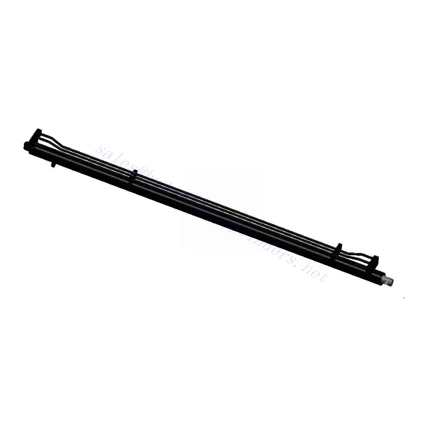
Mobile Crane Outrigger Cylinder
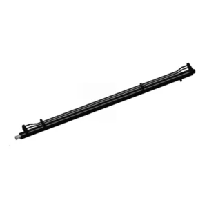
The mobile crane outrigger cylinder is a critical component in mobile crane systems, designed to provide stability and safety during lifting operations. This hydraulic cylinder is specifically engineered to extend and retract the outrigger beams of the crane, ensuring a solid foundation and preventing tipping or instability.
The mobile crane outrigger cylinder ensures stability and safety during lifting operations. With its robust construction, hydraulic extension and retraction, stability enhancement, and built-in safety features, this hydraulic cylinder empowers crane operators to establish a secure foundation and prevent tipping or instability while handling heavy loads. By following proper usage methods and adhering to recommended maintenance practices, operators can maximize the longevity and performance of the mobile crane outrigger cylinder, contributing to safer and more efficient lifting operations. Choose this essential hydraulic component to elevate the stability and safety of your mobile crane, enabling successful and hassle-free lifting at new heights.
Mobile Crane Outrigger Cylinder Key Characteristics:
- Vankka rakenne:
- The mobile crane outrigger cylinder is constructed with high-quality materials, ensuring durability and reliability even in demanding working conditions.
- It is designed to withstand heavy loads, vibrations, and exposure to environmental elements, providing long-lasting performance.
- Hydraulic Extension and Retraction:
- This cylinder utilizes hydraulic power to extend and retract the outrigger beams of the mobile crane.
- The hydraulic system allows for precise control and smooth operation, enabling quick setup and adjustment of the outriggers.
- Stability Enhancement:
- By extending the outrigger beams, the mobile crane outrigger cylinder significantly increases the crane’s stability during lifting operations.
- It provides a broader support base, minimizing the risk of tipping or toppling, especially when handling heavy loads or operating on uneven terrain.
- Safety Features:
- The outrigger cylinder is equipped with safety mechanisms such as locking pins or valves to secure the extended outrigger beams in position.
- These features prevent accidental retraction and ensure the crane’s stability throughout lifting.
Mobile Crane Outrigger Cylinder Parameter:
| Product Name | Mobile Crane Outrigger Cylinder |
| Features: | Support the weight of the entire equipment when the crane is lifting |
| Bore diameter: | 70mm~360mm |
| Rod diameter: | 45mm~320mm Stroke≤800mm |
| Pressure: | Maximum 42MPa |
| Outrigger Cylinder Applications: | Mobile Crane |
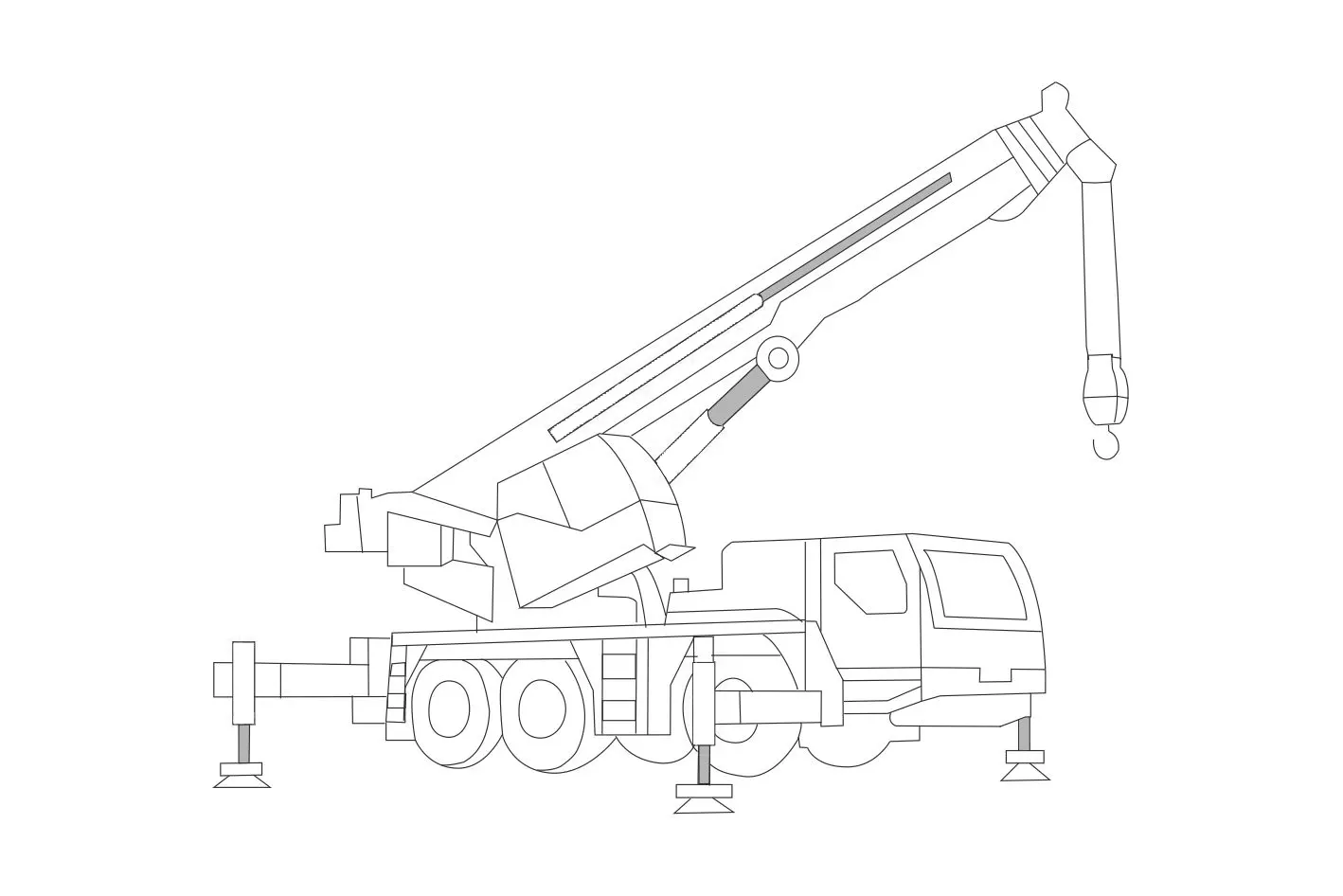
Mobile Crane Identification Diagram:
Usage Method Of Mobile Crane Outrigger Cylinder:
- Site Assessment:
- Before deploying the outriggers, thoroughly assess the work area to identify any potential hazards or challenges.
- Ensure that the ground is stable and capable of supporting the crane’s weight and lifting loads.
- Familiarize with Controls:
- Understand the control mechanisms and operating procedures specific to your mobile crane model.
- Identify the controls responsible for extending and retracting the outrigger beams.
- Extending the Outriggers:
- Activate the control to extend the mobile crane outrigger cylinder, allowing the outrigger beams to reach their extended position.
- Monitor the position of the outrigger beams, ensuring they are correctly aligned and securely locked in place.
- Retracting the Outriggers:
- When the lifting operation is complete, activate the control to retract the outrigger beams.
- Ensure that the outriggers retract smoothly and uniformly, aligning with the crane’s body for safe transportation.
How To Bleed Air From Tractor Hydraulic System?
Bleeding air from a tractor hydraulic system is crucial to maintain optimal performance and prevent issues like reduced responsiveness and erratic behavior. Here’s a step-by-step guide on how to bleed air from a tractor hydraulic system:
- Identify Bleed Points:
- Determine the locations in the hydraulic system where air can accumulate. Common bleed points include air bleed valves, bleed screws, or fittings with removable caps.
- Consult the tractor’s manual or manufacturer guidelines for specific information on bleed points.
- Prepare the System:
- Ensure that the tractor is turned off and the hydraulic pressure is fully released.
- Locate the hydraulic fluid reservoir and check the fluid level. Maintain the fluid level within the recommended range.
- Start at the Lowest Point:
- Begin the bleeding process at the lowest point in the hydraulic system, where air can accumulate.
- Loosen the air bleed valve or remove the fitting cap to expose the bleed screw.
- Open the Bleed Point:
- Use an appropriate tool, such as a wrench or screwdriver, to slowly open the air bleed valve or loosen the bleed screw.
- Be cautious not to completely remove the valve or screw, as it may result in fluid leakage.
- Purge the Air:
- As the bleed point is opened, air bubbles may start to escape along with hydraulic fluid.
- Allow the air to purge from the system until a steady flow of fluid without air bubbles is observed.
- Have a container or absorbent material ready to catch any fluid that may spill during this process.
- Close the Bleed Point:
- Once the air is purged, close the air bleed valve or tighten the bleed screw securely.
- Ensure that the valve or screw is properly sealed to prevent any further air entry.
- Move to the Next Bleed Point:
- Proceed to the next highest point in the system where air can accumulate and repeat steps 4-6.
- Continue bleeding the system at each identified bleed point, working your way up to the highest point.
- Check Fluid Level:
- Throughout the bleeding process, monitor the fluid level in the reservoir and top up if necessary.
- Use the recommended hydraulic fluid specified in the tractor’s manual or by the manufacturer.
- Test and Verify:
- After bleeding all the identified points, start the tractor and operate the hydraulic system to ensure proper functionality.
- Check for any signs of spongy response, abnormal noises, or erratic behavior.
- If issues persist, repeat the bleeding process or consult a qualified technician for further assistance.
Tehtaan kapasiteetti ja kapasiteetti:
(1) Kokoonpano
Meillä on ensiluokkainen riippumaton tutkimus- ja kehitystyön kokoonpanoalusta. Hydraulisylinterien tuotantopajassa on neljä puoliautomaattista nostosylinterin kokoonpanolinjaa ja yksi automaattinen kallistussylinterin kokoonpanolinja, joiden suunniteltu vuotuinen tuotantokapasiteetti on 1 miljoona kappaletta. Erikoissylinterin työpaja on varustettu erilaisilla eritelmillä puoliautomaattisen puhdistusasennuksen kokoonpanojärjestelmällä, jonka suunniteltu vuotuinen tuotantokapasiteetti on 200 000, ja se on varustettu kuuluisilla CNC-työstölaitteilla, työstökeskuksella, korkean tarkkuuden sylinterin käsittelyyn tarkoitetuilla erityislaitteilla, robottihitsauskoneella, automaattisella puhdistuslaitteella, automaattisella sylinterin kokoonpanokoneella ja automaattisella maalaustuotantolinjalla. Olemassa olevat kriittiset laitteet yli 300 sarjaa (sarjaa). Laiteresurssien optimaalinen kohdentaminen ja tehokas käyttö varmistavat tuotteiden tarkkuusvaatimukset ja täyttävät tuotteiden laatuvaatimukset.


(2) Koneistus
Työstöpaja on varustettu räätälöidyllä kaltevalla kiskosorvauskeskuksella, työstökeskuksella, suurnopeus-hiontakoneella, hitsausrobotilla ja muilla vastaavilla laitteilla, joilla voidaan käsitellä sylinteriputkia, joiden sisähalkaisija on enintään 400 mm ja enimmäispituus on 6 metriä.

(3) Hitsaus

(4) Maalaus ja pinnoitus
Pienillä ja keskisuurilla sylinterin automaattisilla vesipohjaisilla maalipinnoituslinjoilla automaattisen robotin lastaus- ja purku- ja automaattisen ruiskutuksen saavuttamiseksi, suunnittelukapasiteetti on 4000 kappaletta vuorossa;
Meillä on myös puoliautomaattinen maalauslinja suurille sylintereille, joka toimii voimaketjulla ja jonka suunnittelukapasiteetti on 60 laatikkoa työvuorossa.


(5) Testaus
Meillä on ensiluokkaiset tarkastustilat ja testialustat, joilla varmistetaan, että sylinterin suorituskyky täyttää vaatimukset.

We are one of the best hydraulic cylinder manufacturers. We can offer comprehensive hydraulic cylinders. We also provide corresponding maatalousvaihteistot. We have exported our products to clients worldwide and earned a good reputation because of our superior product quality and after-sales service. We welcome customers at home and abroad to contact us to negotiate business, exchange information, and tehdä yhteistyötä kanssamme!
Tutustu VR-tehtaaseemme:
Tutustu VR-tehtaaseemme seuraavalla kierroksella
Miten haarukkatrukin hydraulisylinteri toimii?
Hydraulisylinteri Sovellus:
