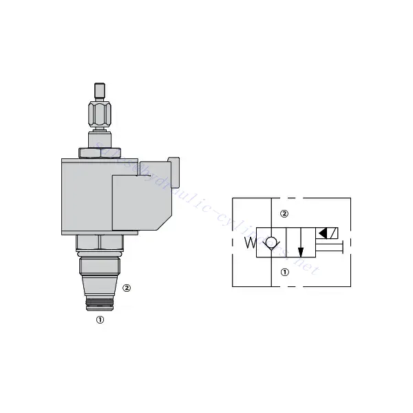
30SD08-20J Solenoid Directional Valve
Jako jeden z výrobců, dodavatelů a vývozců hydraulických válců nabízíme hydraulické válce a mnoho dalších výrobků.
Kontaktujte nás, prosím, pro podrobnosti.
Mail:sales@hydraulic-cylinders.net
Výrobce, dodavatel a vývozce hydraulických válců.
30SD08-20J Solenoid Directional Valve
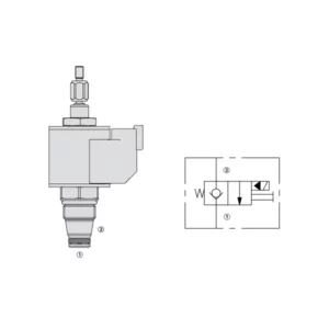
Introducing the 30SD08-20J solenoid directional valve—a state-of-the-art hydraulic component designed to deliver precise control and efficient operation in a wide range of industrial applications. With its advanced features, reliable performance, and sturdy construction, this valve offers an optimal solution for directing hydraulic fluid flow.
The 30SD08-20J solenoid directional valve offers precise control and efficient operation for hydraulic systems. With its versatile functionality, high flow capacity, quick response time, and sturdy construction, this valve provides optimal fluid flow control, enhancing system performance and productivity. By following the recommended usage methods and maintenance guidelines, you can maximize the potential of this valve and achieve improved efficiency in your hydraulic applications. Upgrade your hydraulic system today with the 30SD08-20J solenoid directional valve and experience enhanced control, reliability, and precision.
30SD08-20 Solenoid Directional Valve Key Characteristics:
- Versatile Functionality:
- The 30SD08-20J solenoid directional valve offers versatile functionality, making it suitable for various hydraulic applications.
- It enables precise control of fluid flow, allowing for efficient operation and enhanced system performance.
- High Flow Capacity:
- With its high flow capacity, this valve can handle substantial fluid volumes, making it ideal for applications requiring large flow rates.
- Its ability to accommodate high flow rates ensures efficient and reliable operation, even in demanding industrial environments.
- Quick Response Time:
- The solenoid technology incorporated in this valve ensures a rapid response time, enabling swift and accurate control of hydraulic fluid flow.
- The quick response time enhances system efficiency and enables precise adjustments during operation.
- Sturdy Construction:
- The 30SD08-20J solenoid directional valve is built to withstand harsh operating conditions and provide long-lasting performance.
- Its robust construction and high-quality materials ensure durability, minimizing downtime and reducing maintenance requirements.
30SD08-20J Solenoid Directional Valve Parameter:
| Rated pressure | 207 bar(3000 psi) |
| Proof pressure | 255 bar (3700 psi) |
| Peak flow | See performance chart |
| Fluid | Mineral-based or synthetics with lubricating properties |
| Fluid temperature range ℃ | -54 to 107 ℃ (Polyurethane seals) |
| -40 to 100 ℃ (Buna N seals) | |
| -26 to 204 ℃ (Fluorocarbon seals) | |
| Viscosity range | 7.4 to 420 mm2/s |
| Degree of contamination | The minimum pollution level is ISO4406 level 20/18/14, and level 17/15/13 is recommended to prolong the service life |
| Internal Leakage | ≤ 0.15 mL/min (3 drops/min) @207bar |
| Cavity | VC08-2 |
| Coil Duty Rating | Continuous from 85% to 115% of nominal voltage |
| Initial Coil Current Draw at 20℃ | 1.4A at 12VDC; 0.7A at 24VDC |
| Minimum pull-in voltage | 85% of nominal at 207 bar (3000 psi) |
30SD08-20J Solenoid Directional Valve Advantages:
• Continuous-duty rated coil
• Manual override standard
• Optional waterproof E-Coils rated up to IP69K
• Industry common cavity
• Hardened parts for long life
Usage Method Of 30SD08-20J Solenoid Directional Valve:
- System Evaluation:
- Begin by evaluating your hydraulic system’s requirements, including factors such as flow rate, pressure, and system dynamics.
- Determine if the 30SD08-20J Solenoid Directional Valve aligns with the specific needs of your system.
- Valve Selection:
- Select the appropriate variant of the 30SD08-20J solenoid directional valve based on your system parameters and performance requirements.
- Consider factors such as flow capacity, pressure ratings, and compatibility with other system components for optimal functionality.
- Installation:
- Follow the manufacturer’s installation instructions carefully to ensure proper placement and secure mounting of the valve.
- Position the valve correctly within the hydraulic system, considering factors such as fluid flow direction and accessibility for maintenance.
- Electrical Connections:
- Connect the solenoid valve to the appropriate power source according to the manufacturer’s specifications.
- Ensure that the electrical connections are secure and comply with safety standards.
How To Replace A Shower Valve Cartridge?
Replacing a shower valve cartridge can help resolve leaks, temperature control problems, or a malfunctioning valve. Here is a step-by-step guide to help you replace a shower valve cartridge:
- Please turn off the Water Supply: Locate the main water shut-off valve for your shower and turn it off to cut off the water supply. This is crucial to prevent any water flow while you work on replacing the cartridge.
- Remove the Shower Handle: Most shower handles have a screw or decorative cap at the base. Use a screwdriver or gently pry off the lid to access the screw. Unscrew and remove the handle by pulling it straight out.
- Access the Cartridge: Depending on your shower valve model, you may need to remove additional parts to access the cartridge. This can include a trim plate or escutcheon that covers the valve. Use a screwdriver to remove any screws holding these parts and gently pull them away.
- Remove the Retaining Clip or Nut: Look for a retaining clip or nut that secures the cartridge. It is usually located on the top of the cartridge. Use pliers or an adjustable wrench to loosen and remove the clip or nut.
- Remove the Old Cartridge: With the retaining clip or nut removed, you can pull out the old cartridge. Grip the cartridge firmly and pull it straight out of the valve body. If it is stuck, you may need to wiggle it gently or use a cartridge removal tool designed for your shower valve model.
- Prepare the New Cartridge: Take the new cartridge and ensure it matches the model and make of your shower valve. Check if any rubber seals or o-rings need to be installed on the cartridge according to the manufacturer’s instructions.
- Install the New Cartridge: Insert the new cartridge into the valve body, aligning it correctly. Push it in firmly until it is fully seated. Ensure it is oriented correctly, matching any alignment marks or grooves if applicable.
- Secure the Cartridge: If your cartridge requires a retaining clip, slide it back into place over the top of the cartridge if it uses a nut, carefully thread and tighten it by hand or with pliers. Be cautious not to overtighten, as it may damage the cartridge.
- Reassemble and Test: Reassemble the shower valve by following the steps in reverse order. Ensure that all parts are securely in place. Turn on the water supply and test the shower to check for leaks, proper temperature control, and overall functionality.
Capability & Capacity Of Factory:
(1) Assembly
We have a first-class independent research and development assembly platform. The hydraulic cylinder production workshop has four semi-automatic lifting cylinder assembly lines and one automatic tilt cylinder assembly line, with a designed annual production capacity of 1 million pieces. The special cylinder workshop is equipped with various specifications of a semi-automatic cleaning assembly system with a designed annual production capacity of 200,000 and equipped with famous CNC machining equipment, a machining center, a high-precision cylinder processing special equipment, a robot welding machine, an automatic cleaning machine, automatic cylinder assembly machine, and automatic painting production line. Existing critical equipment of more than 300 sets (sets). The optimal allocation and efficient use of equipment resources ensure the accuracy requirements of products and meet the high-quality needs of products.


(2) Machining
The machining shop is equipped with a customized inclined rail turning center, machining center, high-speed honing machine, welding robot, and other related equipment, which can handle the processing of cylinder tubes with a maximum inner diameter of 400mm and a maximum length of 6 meters.

(3) Welding

(4) Painting & coating
With small and medium-sized cylinder automatic water-based paint coating lines, to achieve automatic robot loading and unloading and automatic spraying, the design capacity of 4000 pieces per shift;
We also have a semi-automatic paint production line for large cylinders powered by a power chain, with 60 cases per shift design capacity.


(5) Testing
We have first-class inspection facilities and test beds to ensure that the performance of the cylinder meets the requirements.

We are one of the best hydraulic cylinder manufacturers. We can offer comprehensive hydraulic cylinders. We also provide corresponding agricultural gearboxes. We have exported our products to clients worldwide and earned a good reputation because of our superior product quality and after-sales service. We welcome customers at home and abroad to contact us to negotiate business, exchange information, and cooperate with us!
Take a Tour of Our VR Factory:
Take a tour of our VR factory with the following
How Does Forklift Hydraulic Cylinder Work?
Hydraulic Cylinder Application:
