30SD08-25 Solenoid Directional Valve
Като един от производителите, доставчиците и износителите на хидравлични цилиндри, ние предлагаме хидравлични цилиндри и много други продукти.
Моля, свържете се с нас за подробности.
Поща:sales@hydraulic-cylinders.net
Производител, доставчик и износител на хидравлични цилиндри.
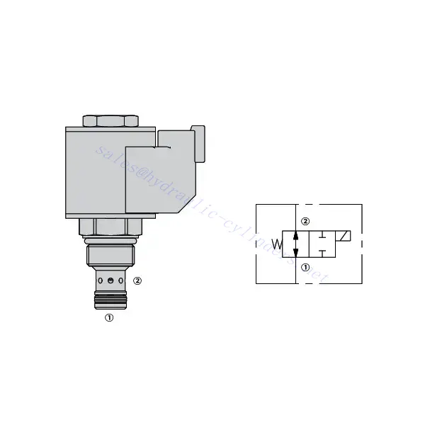
30SD08-25 Solenoid Directional Valve

Welcome to the world of precision hydraulic control with the 30SD08-25 solenoid directional valve. Designed to meet the demands of diverse industrial applications, this cutting-edge valve offers exceptional performance, reliability, and efficiency.
The 30SD08-25 solenoid directional valve is your gateway to enhanced hydraulic control. With its precise fluid flow management, versatility, high flow capacity, and quick response time, this valve empowers your hydraulic system to reach new levels of performance and efficiency. By following the recommended usage methods and maintenance guidelines, you can harness the full potential of the 30SD08-25 solenoid directional valve and achieve seamless control, increased productivity, and improved overall performance. Elevate your hydraulic system today with the 30sd08-25 solenoid directional valve and experience the power of precise hydraulic control.
30SD08-25 Solenoid Directional Valve Characteristics:
- Precise Fluid Flow Management:
- The 30SD08-25 solenoid directional valve empowers you with precise control over fluid flow in your hydraulic system.
- With its accurate flow management capabilities, this valve ensures optimal performance and responsiveness.
- Versatile Applications:
- This valve is designed to cater to various industrial applications, making it a versatile solution for hydraulic systems.
- Whether you require precise control in manufacturing, construction, or automation, the 30SD08-25 solenoid directional valve delivers the needed performance.
- High Flow Capacity:
- With its high flow capacity, this valve can handle significant fluid volumes, enabling efficient and reliable operation.
- The valve’s ability to accommodate high flow rates ensures that your hydraulic system operates smoothly, even in demanding conditions.
- Quick Response Time:
- Equipped with state-of-the-art solenoid technology, the 30SD08-25 solenoid directional valve boasts an impressive response time.
- Experience rapid and accurate control adjustments, allowing seamless fluid flow direction changes and improved system efficiency.
30SD08-25 Solenoid Directional Valve Parameter:
| Rated pressure | 207 bar(3000 psi) | |
| Peak flow | 9.5 L/min (2.5 gpm) | |
| Internal Leakage | ≤ 82 mL/min @207 bar | |
| Coil Duty Rating | Continuous from 85% to 115% of nominal voltage | |
| Initial Coil Current Draw at 20℃ | 1.4A at 12VDC; 0.7A at 24VDC | |
| Minimum pull-in voltage | 85% of nominal at 207 bar (3000 psi) | |
| Cavity | VC08-2 | |
| Fluid | Mineral-based or synthetics with lubricating properties | |
| Fluid temperature range ℃ | -54 to 107 ℃ (Polyurethane seals) | |
| -40 to 100 ℃ (Buna N seals) | ||
| -26 to 204 ℃ (Fluorocarbon seals) | ||
| Viscosity range | 7.4 to 420 mm2/s | |
| Degree of contamination | The minimum pollution level is ISO4406 level 20/18/14, and level 17/15/13 is recommended to prolong the service life | |
30SD08-25 Solenoid Directional Valve Advantages:
• Continuous-duty rated coil
• Both ports may be fully pressurized
• Efficient wet-armature construction
• Cartridges are voltage interchangeable
• Optional waterproof E-Coils rated up to IP69K
• Industry common cavity
• Hardened parts for long life and low leakage
Usage Method Of 30SD08-25 Solenoid Directional Valve:
- System Evaluation:
- Begin by evaluating the specific requirements of your hydraulic system, considering factors such as flow rates, pressure levels, and system dynamics.
- Assess whether the 30SD08-25 solenoid directional valve aligns with your system’s needs and performance expectations.
- Valve Selection:
- Select the appropriate variant of the 30SD08-25 solenoid directional Valve based on your system parameters and performance requirements.
- Consider factors such as flow capacity, pressure ratings, and compatibility with other system components for optimal functionality.
- Installation:
- Follow the manufacturer’s installation instructions diligently to ensure proper placement and secure valve mounting.
- Position the valve correctly within the hydraulic system, considering fluid flow direction and accessibility for maintenance purposes.
- Electrical Connections:
- Connect the solenoid valve to the designated power source per the manufacturer’s specifications.
- Ensure the electrical connections are secure, adhering to safety standards and regulations.
How To Install A Hydraulic Pressure Relief Valve?
Installing a hydraulic pressure relief valve is a crucial step in ensuring the safety and proper functioning of a hydraulic system. Here’s a step-by-step guide on how to install a hydraulic pressure relief valve:
- Identify the Valve: Determine the specific type and model of the hydraulic pressure relief valve you work with. Ensure it is suitable for your application and compatible with your hydraulic system requirements.
- Gather the Required Tools and Materials: Collect the necessary tools and materials, including appropriate hydraulic fittings, adapters, wrenches, Teflon tape (thread sealant), and a pressure gauge if needed. Refer to the manufacturer’s instructions for any specific tools or components required.
- Prepare the Hydraulic System: Shut down the hydraulic system and relieve pressure by activating the relief valve or retracting hydraulic cylinders. This step is crucial for safety and prevents accidental movement or hydraulic fluid release.
- Identify the Pressure Relief Point: Determine the optimal location to install the hydraulic pressure relief valve in your hydraulic system. It should be positioned downstream of the pump before any sensitive components to protect them from excessive pressure. Consult the hydraulic system schematic or seek professional advice if necessary.
- Mount the Valve: Securely mount the hydraulic pressure relief valve in the chosen location using appropriate brackets or clamps. Ensure the valve is positioned correctly, aligning the inlet and outlet ports with the flow direction. Follow the manufacturer’s instructions for specific mounting requirements.
- Connect the Inlet and Outlet Ports: Attach hydraulic hoses or tubing to the inlet and outlet ports of the relief valve. Use suitable hydraulic fittings and adapters to create a leak-free connection. Apply Teflon tape or thread sealant to the male threads of the fittings to ensure a secure and sealed connection. Tighten the connections using wrenches to avoid leaks, but be careful not to overtighten.
- Set the Pressure Relief Setting: Most hydraulic pressure relief valves come with an adjustable pressure relief setting. Adjust the relief valve to the desired pressure relief point using the manufacturer’s guidelines. Some valves may require a pressure gauge to accurately set the relief pressure. Install the pressure gauge temporarily, if needed, and adjust the relief valve until the desired pressure is achieved.
- Test the System: Once the hydraulic pressure relief valve is installed, slowly restore hydraulic system pressure. Monitor the pressure gauge or observe the system behavior to ensure that the relief valve functions correctly. The relief valve should open and divert excess pressure when it reaches the set point, preventing damage to the system.
- Monitor and Maintain: Regularly inspect the hydraulic pressure relief valve for any signs of leakage, damage, or reduced performance. Clean the valve and surrounding area to remove dirt and debris that may affect its operation. Follow the manufacturer’s recommended maintenance schedule and guidelines to ensure optimal performance and longevity.
Capability & Capacity Of Factory:
(1) Assembly
We have a first-class independent research and development assembly platform. The hydraulic cylinder production workshop has four semi-automatic lifting cylinder assembly lines and one automatic tilt cylinder assembly line, with a designed annual production capacity of 1 million pieces. The special cylinder workshop is equipped with various specifications of a semi-automatic cleaning assembly system with a designed annual production capacity of 200,000 and equipped with famous CNC machining equipment, a machining center, a high-precision cylinder processing special equipment, a robot welding machine, an automatic cleaning machine, automatic cylinder assembly machine, and automatic painting production line. Existing critical equipment of more than 300 sets (sets). The optimal allocation and efficient use of equipment resources ensure the accuracy requirements of products and meet the high-quality needs of products.


(2) Machining
The machining shop is equipped with a customized inclined rail turning center, machining center, high-speed honing machine, welding robot, and other related equipment, which can handle the processing of cylinder tubes with a maximum inner diameter of 400mm and a maximum length of 6 meters.

(3) Welding

(4) Painting & coating
With small and medium-sized cylinder automatic water-based paint coating lines, to achieve automatic robot loading and unloading and automatic spraying, the design capacity of 4000 pieces per shift;
We also have a semi-automatic paint production line for large cylinders powered by a power chain, with 60 cases per shift design capacity.


(5) Testing
We have first-class inspection facilities and test beds to ensure that the performance of the cylinder meets the requirements.

We are one of the best hydraulic cylinder manufacturers. We can offer comprehensive hydraulic cylinders. We also provide corresponding agricultural gearboxes. We have exported our products to clients worldwide and earned a good reputation because of our superior product quality and after-sales service. We welcome customers at home and abroad to contact us to negotiate business, exchange information, and cooperate with us!
Take a Tour of Our VR Factory:
Take a tour of our VR factory with the following
How Does Forklift Hydraulic Cylinder Work?
Hydraulic Cylinder Application:
